BME280 Temperature, Pressure & Humidity Sensor & python
The BME280 sensor is capable of measuring temperature, pressure and humidity. The sensor communicates with the computer (be that a Raspberry Pi or a microcontroller running micropython) using the I2C (Inter-Integrated Circuit) protocol. Sparkfun provides a detailed description of I2C if you are interested (something for a rainy afternoon…!). To use this on the Raspberry Pi it must be enabled using raspi-config.
In addition the sensor can tell you what (relative) altitude the sensor is at, calculated based on a known pressure and the one which the sensor currently reads. This might be useful, for example, for a drone, where the pressure at groundlevel can be measured and stored before it starts its flight and this measurement then used to calculate how the drone’s altitude changes over its flight.
Let’s have a look at the hardware…
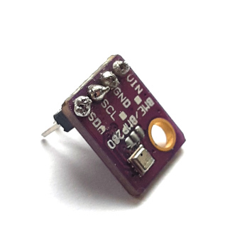
The BME280 has four pins on it labelled VIN (Voltage IN - important: 3.3V!), GND (GrouND), SCL (Serial CLock) and SDA (Serial DAta).
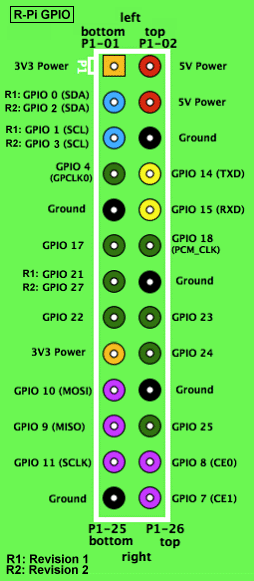
These same pins are also available on the Raspberry Pi. The figure below shows the GPIO pins of the Raspberry Pi 3 and 4 (an iteractive version with lots more resources is available at https://pinout.xyz):
 ]
]
The Raspberry Pi 1 & 2 had only 26 pins and so has a different layout for its GPIO pins:
 ]
]
On both versions of the board, we are interested only in pins 1 (3.3V), 2 (SDA), 3 (SCL) and 5 (Ground). These are on the end of the board furthest from the USB sockets, and on the inside of the board. If in doubt, have a look at https://pinout.xyz.
Wiring up the BME280
We’ve identified the pins we’re interested in and the wiring couldn’t be simpler:
- VIN on the BME280 goes to pin 1 (3V3) on the Raspberry Pi.
- GND on the BME280 goes to pin 5 (ground) on the Pi.
- SCL on the BME280 goes to pin 3 (SCL) on the Pi.
- SDA on the BME280 goes to pin 2 (SDA) on the Pi.
Caution: Do not wire up the BME280 when the Pi is switched on. Connecting the BME280 to a powered up Pi can damage either the Pi or the sensor.
Setting up the Raspberry Pi
If you’ve already used I2C devices on the Raspberry Pi you’re working on, you can skip this section
Once the Raspberry Pi has started up, open a terminal and type the following command:
$ sudo raspi-config
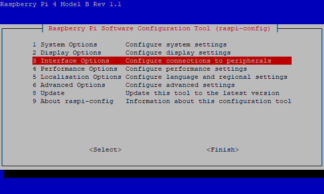
From the raspi-config main menu, select Interface Options by moving the cursor up and down the menu and then pressing <enter>:
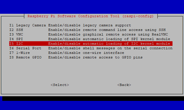
In the Interface Options menu, select I2C:
raspi-config interface options
You will then be asked if you want to enable I2C. You do, so select YES. raspi-config returns to the main menu and you can now select Finish (n.b. you will need to use the left and right arrow keys to get to Finish). If prompted to restart, select yes. Once the Pi has started up again, you can use I2C to talk to sensor.
Writing a python script
First of all, as always, consider making a python virtual environment for working on your project. Details of how to do this are on the python Projects page.
To control the BME280 sensor, we need to download a library using pip. We’re going to the use the one provided by adafruit since I’ve used this before and it works. There are plenty of other libraries available too however…
The following assume that you are already working in a virtual environment (i.e. you have run
source venv/bin/activate(Raspberry Pi/Linux) orvenv\Scripts\activate(Windows))
- if you are not you may have to replace
pipin the commands withpip3. It may also be necessary to use thesudocommand (i.e.sudo pip3...), but if that is necessary, I would strongly recommend using a virtual environment.
(venv) $ pip install adafruit-circuitpython-bme280
This pulls in a number of other packages, including the RPi.GPIO package, which allows us to access the GPIO pins in python.
As a simple example, the following code prints the current temperature to the commandline:
import board
import busio
from adafruit_bme280 import basic as adafruit_bme280    # 1

i2c = busio.I2C(board.SCL, board.SDA)    # 2
bme280 = adafruit_bme280.Adafruit_BME280_I2C(i2c, 0x76)    # 3
temp = bme280.temperature    # 4
print("Temperature: " + str(temp))
The code above should be saved into the file (for example temperature.py). You can run it in a terminal (in which you’ve activated the virtual environment) as follows:
(venv) $ python ./temperature.py
Some explanation of the code (the numbers in comments relate to the numbers belwo):
- The
adafruit_bme280library doesn’t import as nicely as most other libraries. Thefrom adafruit_bme280 import basicpart imports thebasicmodule fromadafruit_bme280. Theas adafruit_bme280part allows us to interact withbasicusing the nameadafruit_bme280. The idea of this is to make the code more readable i2c = busio.I2C(board.SCL, board.SDA)creates an object in python which gives access to the I2C bus on the python, using the pins defined by the board for SCL and SDA.bme280 = adafruit_bme280.Adafruit_BME280_I2C(i2c, 0x76)creates an object representing our BME280 sensor in python using the adafruit library. We tell the library to use thei2cobject we created in (2) to communicate with the BME280. We also tell it that the address of the sensor is0x76(the library is set up for a sensor with I2C address0x77, so its important we tell it the correct address).- Read the temperature. Remember temperatures are reported as
floats. If we want to print the temperature along with a string, we need to convert it to a string (we do this on the line below:str(temp)).
As well as temperature, the adafruit-circuitpython-bme280 allows you to read the humidity and the pressure. The commands, using the same names as the sample above, look like this:
sensor.pressuresensor.humiditysensor.altitude- this assumes sea level pressure of 1013.25 mBar and uses this to determine the altitude.